MIL-PRF-15624G
APPENDIX A
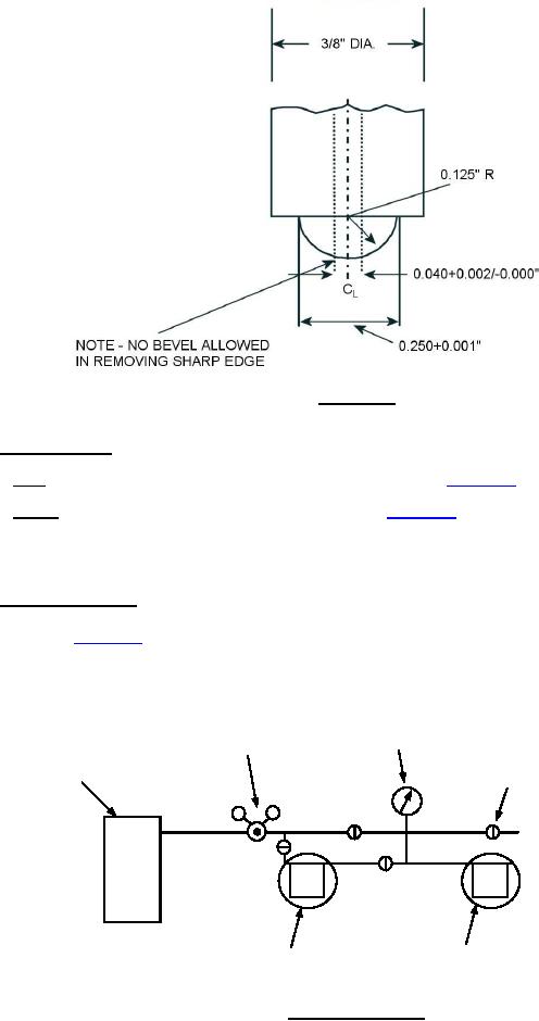
FIGURE A-2. Indentor tip.
A.2.3 Specimen holder. The test specimen holder shall consist of two parts, the holder proper and the base.
A.2.3.1 Base. The base may screw or slide into the holder as indicated on figure A-1.
A.2.3.2 Holder. The holder, of a suitable design as illustrated on figure A-1, shall be 1.132 to 1.134 inch
(28.75 to 28.80 mm) in internal diameter and shall have an opening 1±0.002 inch (25±0.05 mm) in its upper end.
The opening provides a cavity above the specimen that retains fluid on the specimen surface to submerge the
indentor tip.
A.2.4 Air supply apparatus. An air supply apparatus, which consists of a source of compressed air, a
compressed air line, a pressure-regulator valve, pressure gage, and a vent to release the air after the test, shall be
provided as shown on figure A-3. The pressure gage used to determine the sealing pressure shall be capable of
measuring the pressure with an accuracy of ±2 pounds per square inch (psi) (±10 kilopascals(kPa)). NOTE: If a
suitable air supply is not available, compressed gas cylinders containing nitrogen or carbon dioxide may be used.
PRESSURE
CALIBRATED GAUGE
REGULATOR
(5 PSI - DIV.)
RELIEF
AIR SUPPLY
VALVE
TEST JIG (SEE
FOR LOW PRESSURE
FIG. 1)
AIR (SEE FIG. 4)
FIGURE A-3. Air supply apparatus.
10
For Parts Inquires call Parts Hangar, Inc (727) 493-0744
© Copyright 2015 Integrated Publishing, Inc.
A Service Disabled Veteran Owned Small Business